
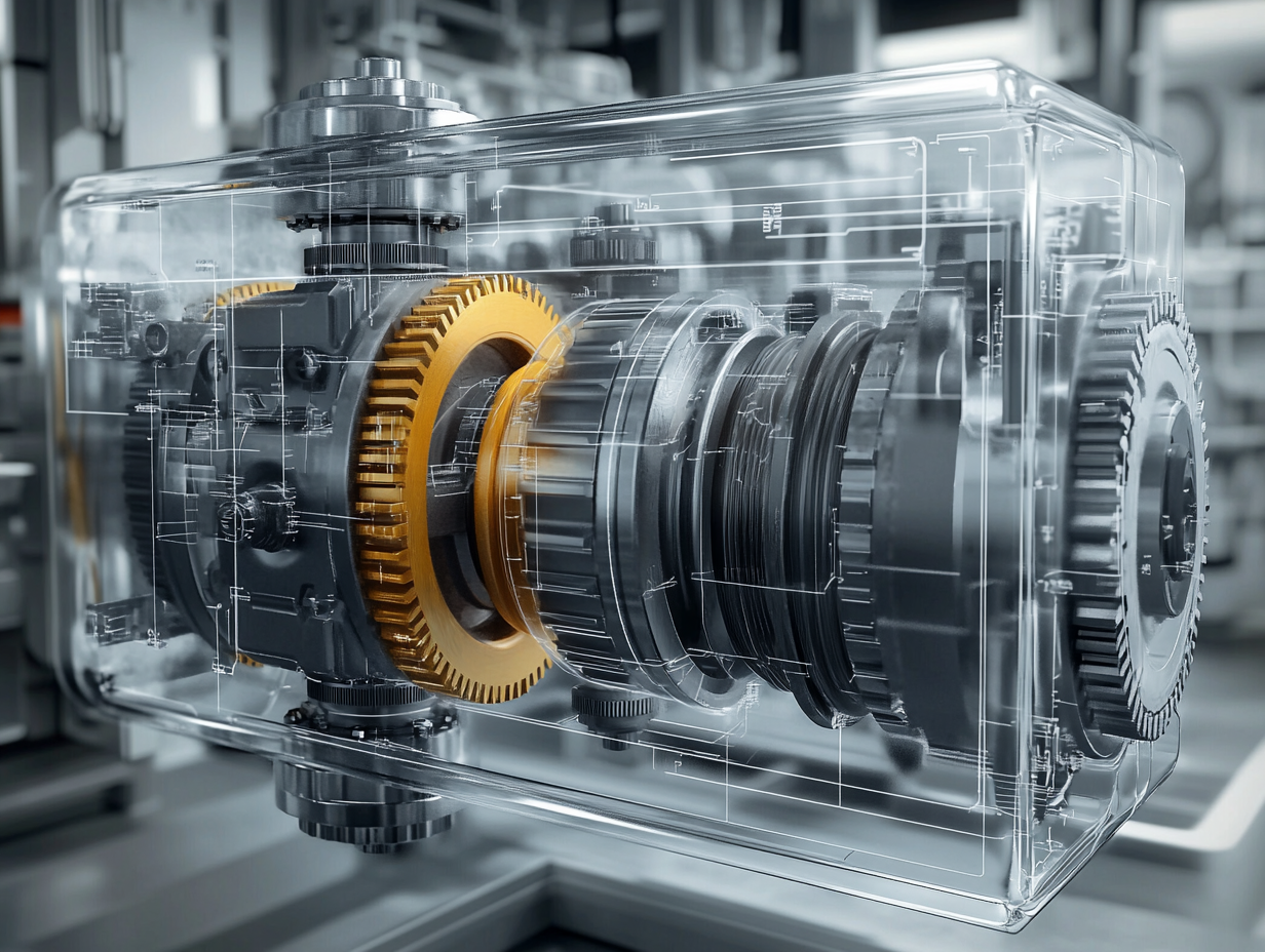
Gear pumps are widely used in hydraulic systems, offering reliability and simplicity in fluid transfer. In marine gearbox systems, gear pumps play a critical role in circulating oil under pressure. This blog explores the design and flow performance of gear pumps using CAD-based modeling, particularly focusing on how gear width and profile selection impact volumetric flow.
Evolvent vs. Cycloid: Understanding Gear Profiles
The tooth profile of a gear significantly affects how it engages with its counterpart and how fluid is transferred. Two common profiles are:
-
Cycloid Profile: Known for quiet operation and lower surface pressure. However, it’s difficult and costly to manufacture due to complex geometry.
-
Involute (Evolvent) Profile: Easier to produce and more tolerant of slight misalignments. Despite having slightly higher wear due to convex-convex contact and higher radial forces, its advantages in standardization and tooling make it the preferred choice in gear pump manufacturing.
For this study, the involute gear profile was selected due to its practical advantages and widespread industrial use.
Evolvent Function Geometry
The involute (evolvent) function is central to understanding gear tooth engagement. It’s generated by unwrapping a taut string from a base circle, resulting in a smooth curve ideal for constant velocity ratio transmission.
Mathematically:
-
The involute function is defined as inv(α) = tan(α) – α (in radians).
-
This function helps in calculating the contact point and pressure angle along the gear teeth.
Understanding these relationships is critical when designing gear teeth in CAD environments.
CAD Modeling and Volumetric Flow Estimation
Using real gear pump dimensions and CAD software, a 3D model was created to calculate the volumetric displacement between gear teeth. Key parameters include:
-
Gear Width (W): Increasing gear width directly increases the volumetric flow rate.
-
Tooth Gap Volume (V): Measured through CAD to find how much fluid is carried per rotation.
-
Pump Speed (RPM): Determines how many volumes per minute are transferred.
The volumetric flow rate is calculated as:
Q = V × N
Where:
Q = Flow rate (cm³/min)
V = Volume between teeth
N = Pump speed (RPM)
Simulation results confirmed that gear width is linearly proportional to flow rate, validating the CAD-based volume calculations.
Accurate flow calculation in gear pumps depends heavily on gear profile selection and detailed CAD modeling. The involute profile, combined with precise dimensional analysis, allows for optimized performance in marine and industrial applications. By modeling gear tooth geometry and simulating volumetric displacement, engineers can predict flow behavior and improve pump efficiency in real-world systems.