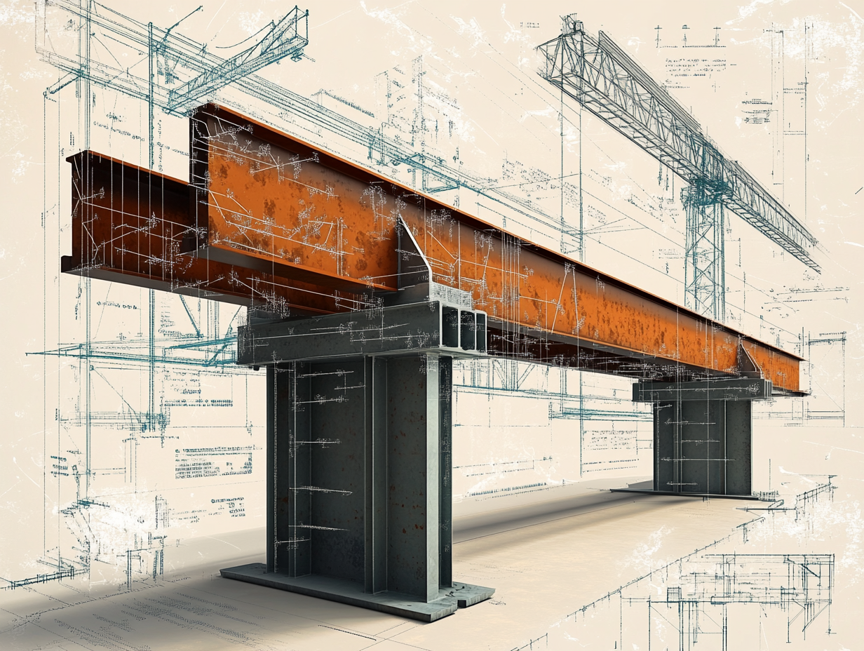

In mining infrastructure and heavy machinery, beams are everywhere from conveyor support frames to equipment platforms and structural walkways. One of the most common configurations is the simply supported beam, where the beam is supported at both ends but free to bend under load.
Understanding how bending moments and shear forces distribute along these beams is essential for ensuring safety, efficiency, and long-term durability.
1. What Is a Simply Supported Beam?
A simply supported beam rests on two supports — either pinned, roller, or a combination of both — without any fixed ends.
This configuration allows rotation at the supports, meaning:
-
Bending moments occur along the span
-
Shear forces are highest near supports
-
No end moments unless there’s partial fixity
2. Bending Moment Distribution
For a beam under a uniform load ww:
Mmax=wL28M_{max} = \frac{wL^2}{8}
-
Maximum bending moment occurs at midspan
-
Moment diagram is parabolic, peaking at center and zero at supports
For a point load PP at midspan:
Mmax=P⋅L4M_{max} = \frac{P \cdot L}{4}
✅ This helps engineers size beams to resist maximum stresses at the right location.
3. Shear Force Distribution
Shear force VV is highest at the supports and decreases towards midspan.
For a uniform load:
Vsupport=wL2V_{support} = \frac{wL}{2}
For a point load at center:
Vsupport=P2V_{support} = \frac{P}{2}
This is critical because excessive shear near supports can cause web buckling in I-beams or shear cracking in reinforced concrete beams.
4. Mining Application Example: Conveyor Support Beam
-
Span L=4 mL = 4 \, \text{m}
-
Uniform load w=2500 N/mw = 2500 \, \text{N/m}
Bending moment at midspan:
Mmax=2500⋅(4)28=5000 NmM_{max} = \frac{2500 \cdot (4)^2}{8} = 5000 \, \text{Nm}
Shear force at support:
Vsupport=2500⋅42=5000 NV_{support} = \frac{2500 \cdot 4}{2} = 5000 \, \text{N}
Engineers then use MmaxM_{max} and VsupportV_{support} to calculate stresses and select beam size.
5. Design Considerations for Mining Environments
✔️ Select cross-sections that handle both bending and shear efficiently (e.g., I-beams, box sections)
✔️ Check both yield strength (bending) and shear capacity
✔️ Factor in dynamic loads from moving equipment or conveyors
✔️ Ensure proper corrosion protection due to dust and moisture
Simply supported beams may seem basic, but they are the backbone of mining infrastructure. Understanding the distribution of bending moments and shear forces allows engineers to design beams that perform reliably, resist failure, and maintain alignment under heavy industrial conditions.

